Igniter Design for HRPG
Prior to serving as President of HRPG, I led the design, fabrication, and testing of the ignition system for our first full-scale liquid rocket engine. This effort involved end-to-end system development, including requirements definition, hardware design, integration with the propulsion and fluids systems, and iterative testing to achieve reliable, repeatable ignition. In the following section, I walk through the design evolution, key engineering decisions, and testing methodology that informed the final system architecture.
System Requirements
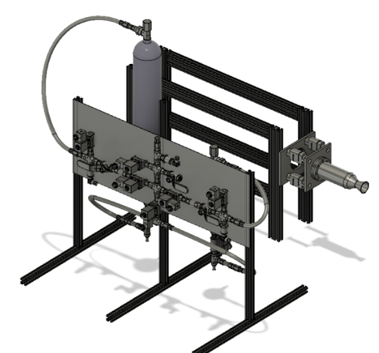
This project aimed to design and build a 500 lbf liquid rocket engine for a flight vehicle using ethanol–LOX, which were selected for its performance, storability, and operational safety in a student environment.
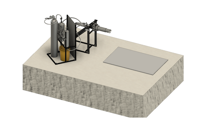
All hardware was required to be testable on a portable static test stand, imposing strict constraints on mass and system complexity. The full propulsion system, including feed lines, valves, instrumentation, and structural interfaces, had to be designed to operate reliably under cryogenic conditions.
A $7,000 total budget required a strong emphasis on manufacturability. Nearly all components were designed for in-house manual machining, minimizing outsourcing and enabling rapid iteration.
The project followed a two-and-a-half-month design–build–test cycle, which directly informed conservative safety margins, simplified plumbing architecture, and material selection. The primary engineering challenge discussed next emerged from operating within these constraints.
Initial Igniter Design (v1)
The initial igniter concept was inspired by torch-ignition architectures commonly used on 40,000 lbf–class liquid rocket engines, aggressively scaled down for a 500 lbf thrust class system. The goal was to implement a proven, high-reliability ignition approach while maintaining compatibility with a compact flight engine.
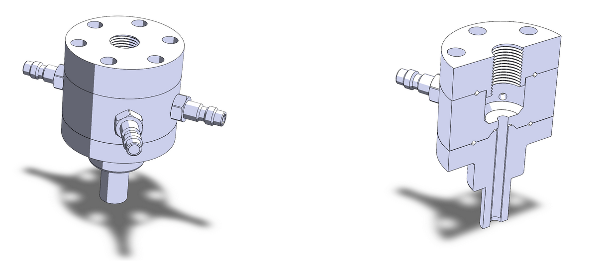
The igniter assembly consisted of three primary components. An upper flange housed a surface-gap spark plug to initiate ignition. Below this, a small precombustion chamber injected and premixed ethanol and oxygen to generate a stable ignition flame. This flame was then delivered through a torch tube that directed the hot plume into the main combustion chamber. To support future iteration, a generic ignitor port was also designed to accept the torch tube, enabling flexibility across different hot-fire configurations. From a functional standpoint, the design appeared robust. Quick-disconnect fittings were incorporated to simplify assembly and servicing, and sealing was handled using Teflon-coated metal O-rings (3/16″ OD, 3/32″ cross-section), which are well-established for high-temperature, high-pressure propulsion environments. In principle, the system offered strong reliability.
However, at this scale, reliability required verifying every sealing interface, threaded joint, and flow path, and the part count increased rapidly. For a student team operating under a compressed schedule, the design began to introduce significant integration and verification overhead. A critical constraint was the exclusive use of NPT threaded fluid connections. NPT fittings rely on tapered threads to provide both structural retention and pressure sealing, which requires the threaded hole to be machined perfectly concentric and perpendicular to the local surface. This exposed a fundamental geometric issue: several ports were located on curved surfaces. Machining NPT threads into curved geometry leads to uneven thread engagement, misalignment, and degraded sealing performance. In the worst case, this can result in leakage or fitting failure under pressure. Although the concept scaled well in theory, this initial design revealed a major manufacturability and sealing challenge that could not be ignored. Addressing this issue became one of the defining engineering problems of the project and directly motivated the subsequent design iterations.
Igniter Design V2
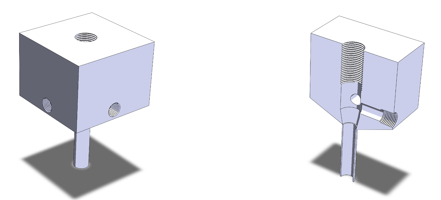
In response to the manufacturability and sealing limitations of the initial design, the ignitor was redesigned around a compact, single-body geometry. This iteration consolidated the entire ignitor into a single solid block, with all internal flow paths and features machined directly into the material.
Brass was selected over aluminum for several reasons. From a manufacturing standpoint, brass is significantly more forgiving during manual machining: taps cut more cleanly, threads are less prone to galling, and tight tolerances are easier to maintain. Thermally, brass also retains strength at higher local temperatures, providing additional margin against transient heating, thermal shock, and localized failure during ignition events.
Transitioning to a single-stock design eliminated multiple failure modes present in the previous architecture. The redesign removed several sealing interfaces, eliminated the need for metal O-rings, and fully resolved the curved-surface threading issue. All NPT ports were relocated to flat, perpendicular faces, substantially improving sealing reliability and enabling straightforward inspection and verification of each threaded connection.
While externally simple, this geometry introduced a new internal complexity. The ignitor tube intersected the combustion cavity at an angle, injector passages required precise alignment, and the spark gap needed to be positioned accurately relative to incoming propellant flow. As a result, the internal channel geometry became difficult to machine cleanly and repeatably, despite the apparent simplicity of the exterior.
Final Igniter Design
After working through the manufacturability challenges of Versions 1 and 2, the ignition problem was revisited from first principles, with structural integrity as the dominant constraint. During this process, we also recognized a fundamental oversight: the engine itself did not include a dedicated ignitor port. Adding one at this stage would have required drilling or welding into the combustion chamber, introducing stress concentrations that were unacceptable at the target chamber pressures without a full FEA-driven structural redesign.
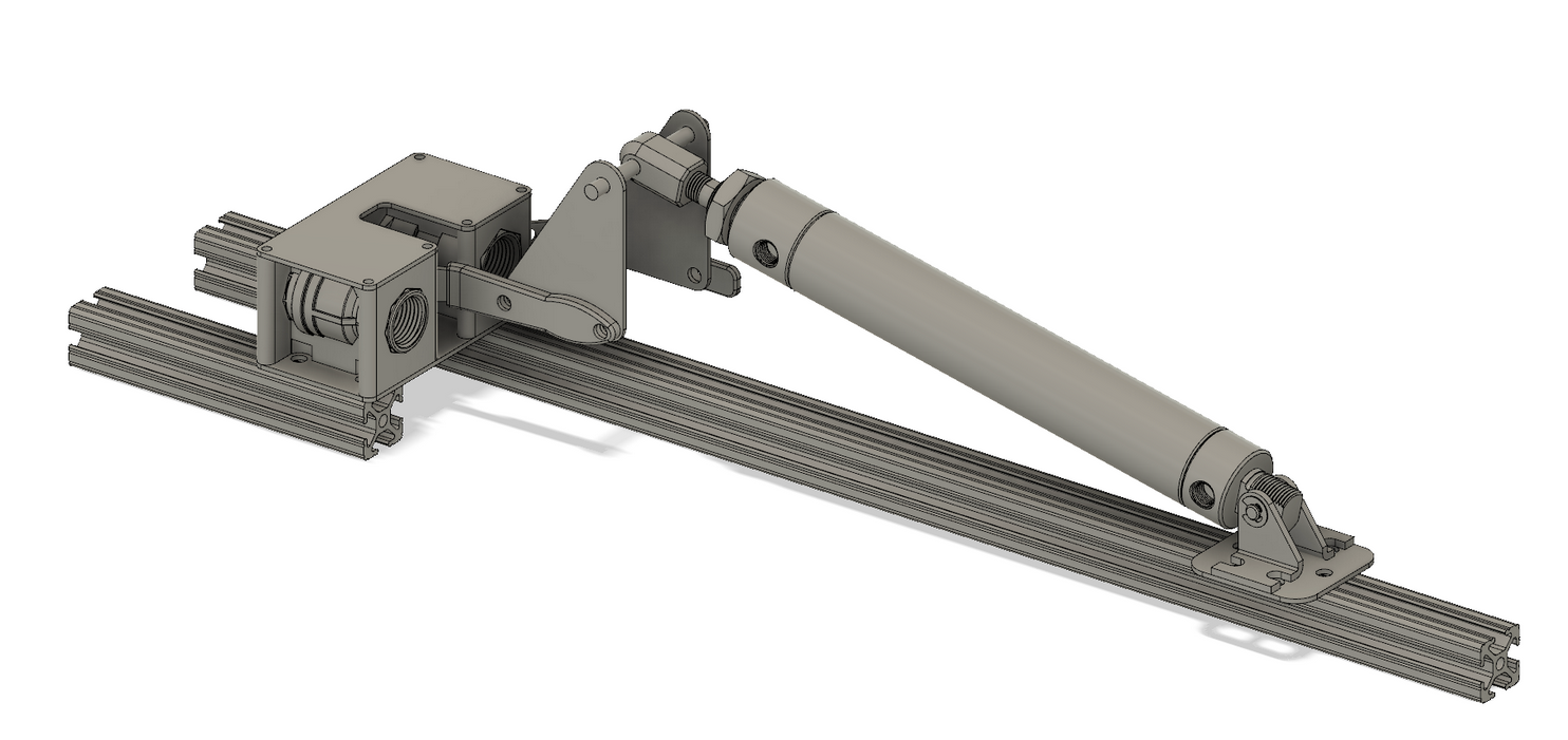
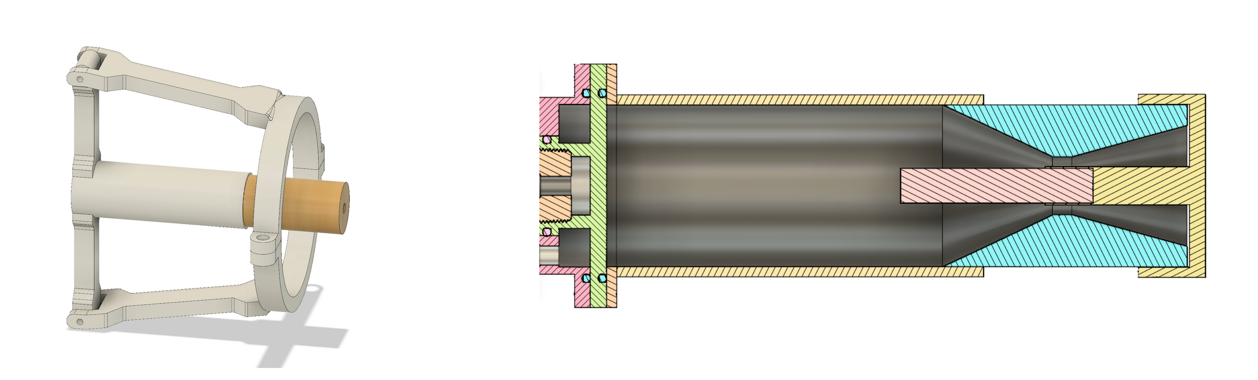
Rather than modifying the chamber wall to accommodate a side-mounted igniter, Version 3 adopted a fundamentally different approach: a throat-mounted, sacrificial igniter that required no additional penetrations into the engine structure.
The ignition source selected was a commercially available Estes E12 solid rocket motor. These motors are inexpensive, readily available, and produce a high-temperature plume sufficient to reliably ignite an ethanol–LOX main engine. This approach eliminated the need for spark systems, propellant feed lines, valves, and sealing interfaces, removing nearly all of the failure modes encountered in earlier designs.
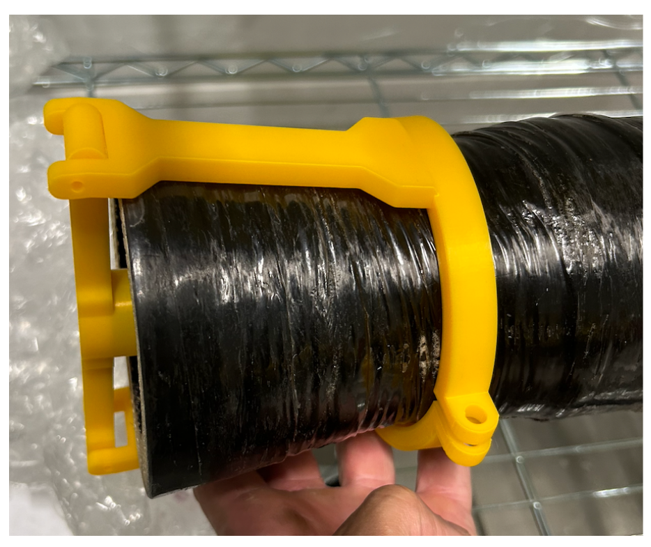
To integrate the igniter, a 3D-printed mounting fixture was designed to seat directly in the chamber throat region. This location allows the igniter hardware to be fully sacrificial, functioning only during the first milliseconds of startup before being shielded from the main flow. Structural loads remain carried by the stainless-steel chamber, rather than by a tapped boss or welded port, preserving chamber integrity.
Finite element analysis (FEA) was used to size the igniter fixture and define its intended failure mode. The mount was designed to withstand the thrust and handling loads of the solid igniter motor, maintaining alignment during startup, while yielding under main-engine thrust. This ensured that the fixture would fail sacrificially rather than transmit excessive loads into the throat or chamber structure.
This design is mechanically simple, structurally conservative, and dramatically reduces fabrication and integration complexity. Version 3 represents a shift from a highly engineered miniature torch igniter to a robust ignition philosophy aligned with the project’s schedule, budget, and reliability goals.

Failure and FMEA
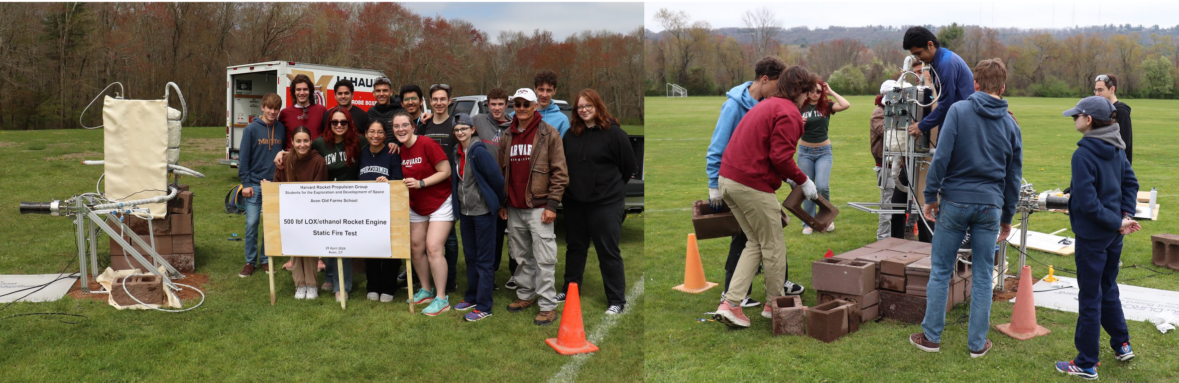
After months of design and fabrication, we reached our first static hot-fire attempt, marking the initial full-system integration of the engine, feed system, and igniter under realistic operating conditions.
The countdown and pressurization sequence executed nominally. During chilldown, we observed a large liquid oxygen plume, indicating proper injector operation and confirming that the oxidizer feed system and plumbing were delivering flow as designed. Although no footage was captured, this validated a significant portion of the fluid system and control logic prior to ignition.
However, when the ignition command was issued, the engine failed to light. While the system reached an active, pressurized state, no combustion occurred. This immediately initiated a structured failure analysis, which identified the igniter system as the primary root cause.
The igniter failure resulted from a combination of electrical activation and field-handling issues. The Estes motor was originally intended to be fired using a dedicated electronic ignition circuit. Due to the tight schedule and budget constraints, the final implementation was hard-wired.
Approximately 700 feet of wire were used to keep personnel outside the hazard zone. During transport and setup, the wire became kinked and crumpled, leading to unexpectedly high loop resistance. As a result, the bridge wire did not receive sufficient current to heat and initiate ignition. A locally powered, microcontroller-based firing unit at the test stand would have mitigated this issue, but there was insufficient margin to design, test, and validate such a system before hot-fire. In hindsight, this highlighted a critical lesson: ignition systems should be electrically isolated, locally powered, and tested under representative field conditions.
While the ignitor was a failure mode, the post-test FMEA revealed the primary faliure mode was in the main valve assembly (MVA). The MVA used two modified manual ball valves actuated via a pneumatic piston. Although the mechanism functioned during ambient bench testing, several latent risks became evident:
The LOX valve body was brass, which is poorly suited for cryogenic oxygen service and likely seized due to thermal contraction and material incompatibility.
The custom mechanical linkage introduced friction, reducing the effective actuation stroke of the piston.
A full cryogenic actuation test was never performed, as facility constraints limited repeated LOX operations. As a result, the first true thermal shock event occurred during the live hot-fire, where the valve locked in place.
Post-test review revealed that commercial off-the-shelf 3-way and 5-way pneumatic valves were available that would have eliminated the custom linkage entirely and significantly improved reliability.
Taken together, the failed hot-fire was a clear demonstration of the importance of component selection, cryogenic compatibility, and test-as-you-fly philosophy in propulsion systems. While the engine did not ignite, the test provided critical validation of the feed system and exposed failure modes that directly informed subsequent design decisions.